

Hardware
EMWaver Air
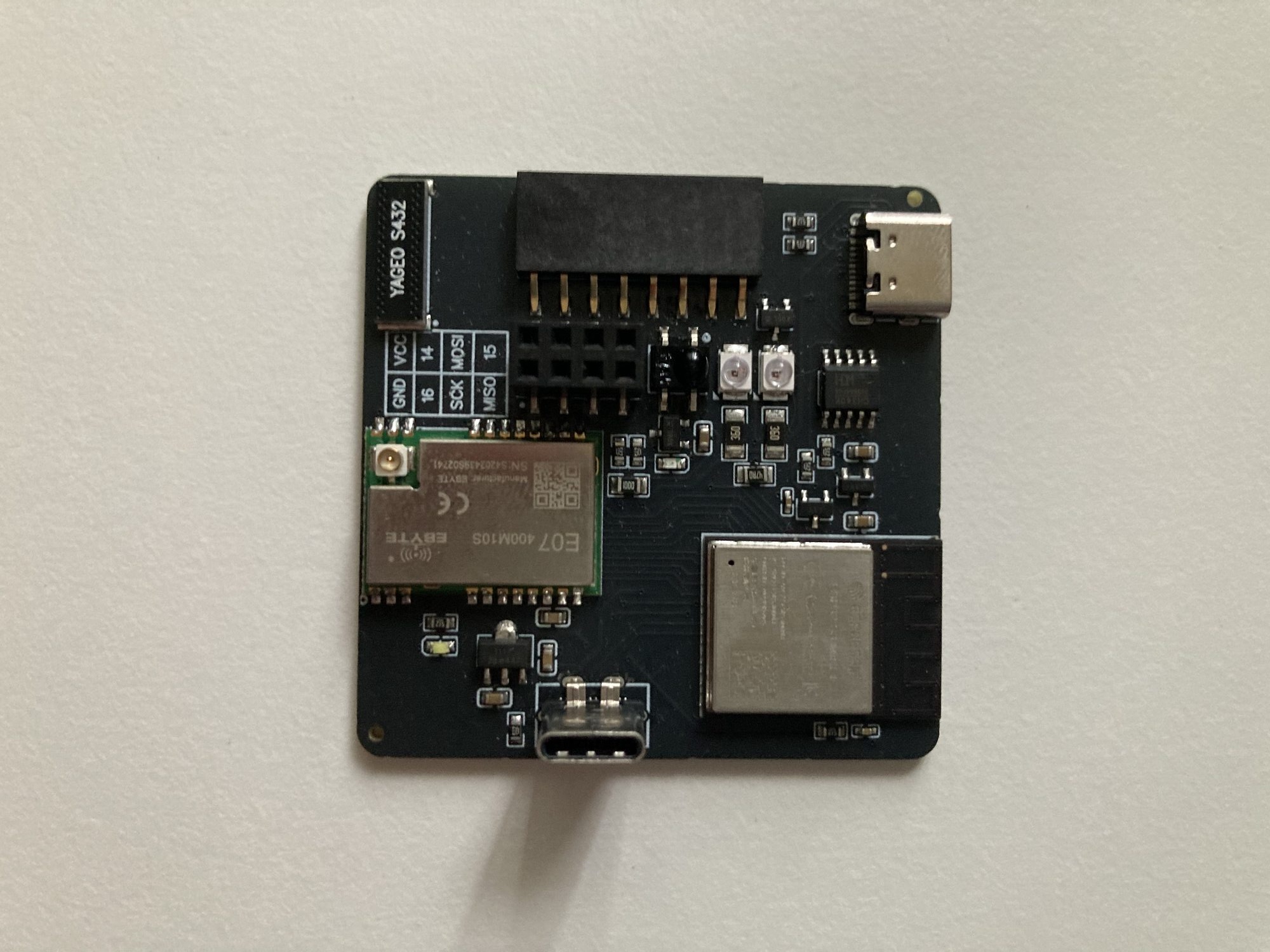
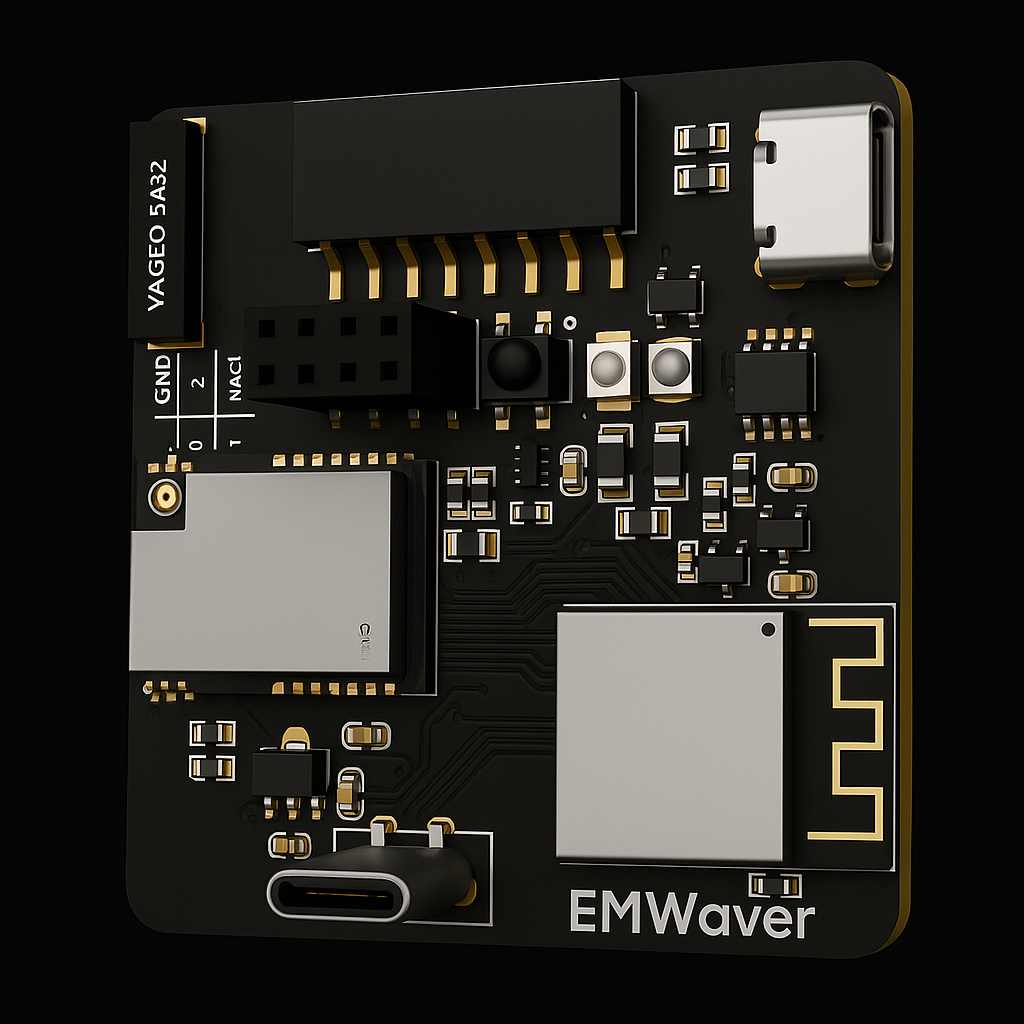
EMWaver Air is the single supported board — an all-in-one ESP32-S3 with a CC1101 sub-GHz radio and infrared RX/TX. The pinout below is the REV 1.0 design.
Specifications
| MCU | ESP32-S3-MINI-1-N8 · dual-core 240 MHz · 8 MB flash · native USB |
| Sub-GHz radio | EBYTE E07-400M10S (CC1101) · 433 MHz chip antenna |
| Infrared | IR receiver + dual IR LEDs (38 kHz carrier) |
| Link | Wi-Fi → outbound wss relay to emwaver.ai |
| Power / USB | USB-C · 5 V → AMS1117-3.3 |
Gallery
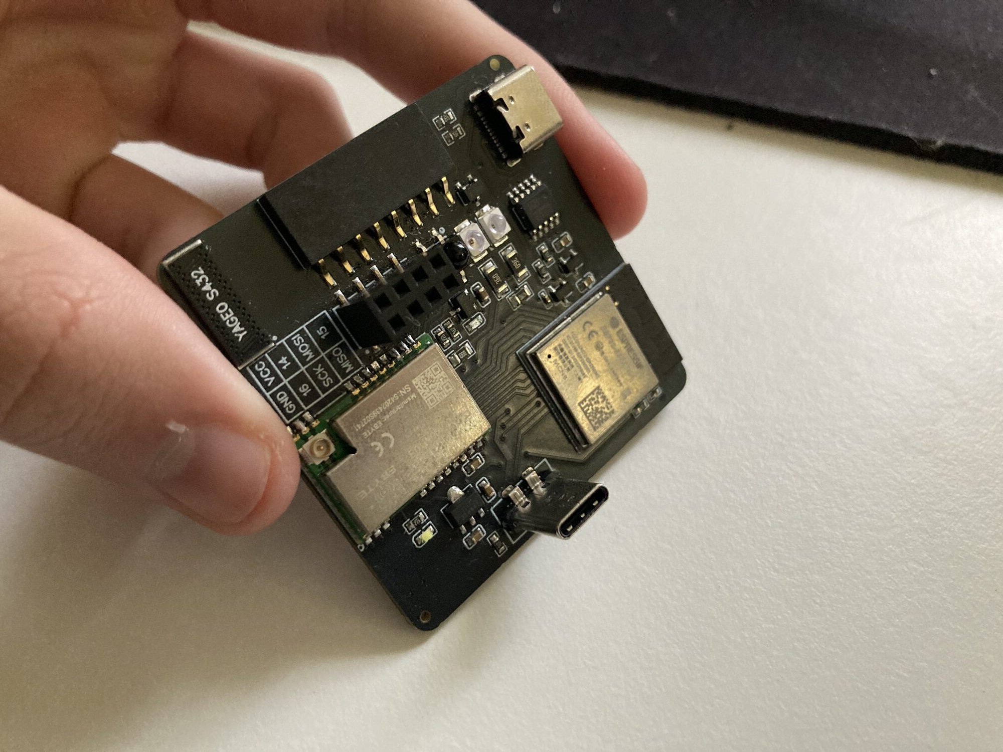
Core pinout
The fixed-function GPIOs used by the firmware.
| GPIO | Function |
|---|---|
GPIO1 | CC1101 GDO0 (async radio data) · onboard white status LED |
GPIO2 | CC1101 GDO2 (radio status) |
GPIO4 | IR transmit — drives the dual IR LEDs |
GPIO5 | IR receive — demodulator input · red status LED |
GPIO10 | SPI NSS / CS — CC1101 radio |
GPIO11 | SPI MOSI |
GPIO12 | SPI SCK |
GPIO13 | SPI MISO |
GPIO19 / GPIO20 | Native USB D− / D+ (USB-C) |
CC1101 sub-GHz radio
The EBYTE E07-400M10S (CC1101) sits on the SPI bus; GDO0 carries the async OOK data the Sub-GHz workspace reads. The on-board white LED follows GDO0, so radio activity is visible.
| CC1101 | Function |
|---|---|
CSN | GPIO10 (shared SPI chip-select) |
SCK | GPIO12 |
MOSI | GPIO11 |
MISO / GDO1 | GPIO13 |
GDO0 | GPIO1 |
GDO2 | GPIO2 |
ANT | 433 MHz chip antenna |
USB & power
- USB-C (native) — D−/D+ on GPIO19/20 for USB device emulation, flashing, and recovery.
- USB-serial — a CH340 path to the UART0 console for USB debugging.
- Power — 5 V in, regulated to 3.3 V by an AMS1117-3.3.
Updates & recovery
The Air updates over the air (A/B partitions with rollback). USB-C is only needed for first-time provisioning, factory flashing, or recovery — there is no manual build/flash loop.