


Set up CC1101 on Windows (433 MHz)
This tutorial shows how to wire a CC1101 module to an ESP32-family EMWaver device, run the built-in cc1101.js script, initialize the radio for 433.92 MHz ASK/OOK transmit mode, and turn on a continuous carrier.
Only transmit on frequencies, power levels, and duty cycles permitted in your location. For bench testing, use a very short antenna, attenuator, or dummy load where appropriate.
What you’ll need
- A Windows 11 PC with the EMWaver app installed.
- An ESP32-family board running EMWaver firmware (ESP32, ESP32-S2, or ESP32-S3).
- A CC1101 433 MHz module.
- Jumper wires and a suitable 433 MHz antenna or controlled test setup.
If the board is not flashed yet, start with the Windows firmware flashing tutorial.
1. Wire the CC1101 to ESP32 SPI
Wire the CC1101 module to the ESP32 SPI pins used by the built-in script defaults. The table below shows the defaults for ESP32-S2 and ESP32-S3. For classic ESP32, the default pins differ: CS=GPIO21, MOSI=GPIO23, MISO=GPIO19, SCK=GPIO18, GDO0=GPIO4. You can change any pin in the script pickers.
| CC1101 pin | ESP32 pin | Purpose |
|---|---|---|
VCC | 3V3 | Power. Do not use 5 V. |
GND | GND | Common ground. |
CSN / CS | GPIO10 | SPI chip select. You can change this in the script picker. |
SI / MOSI | GPIO11 | SPI MOSI. |
SO / MISO | GPIO13 | SPI MISO. |
SCK | GPIO12 | SPI clock. |
GDO0 | GPIO2 | Carrier/data gate. You can change this in the script picker. |
In this example, CS is GPIO10 and GDO0 is GPIO2. If your wiring differs, use the pickers in the script to select the correct pins.
2. Connect the EMWaver device
Connect your flashed EMWaver device to the Windows app. The screenshot below uses BLE, but the same script flow applies over any supported EMWaver transport.
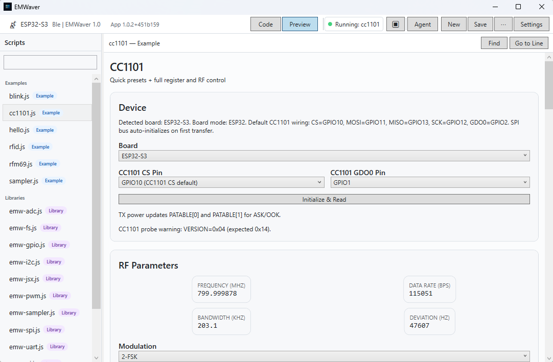
cc1101.js script open. Use the Preview button at the top to render the script UI.3. Open and preview cc1101.js
- Open the Scripts view.
- Select the built-in
cc1101.jsscript. - Click Preview at the top of the script editor.
In the first Device card, confirm the board type and pin selections. For this tutorial, use ESP32, CS = GPIO10, andGDO0 = GPIO2 unless your wiring is different.
4. Initialize the radio and read registers
Click Initialize & Read in the first card. This probes the CC1101 over SPI and reads the current register state into the UI. This is a good first check that wiring and SPI communication are working.
If the probe fails, re-check power, ground, CS, MOSI, MISO, SCK, and the selected CS pin.
5. Scroll to Quick Presets and click Init TX
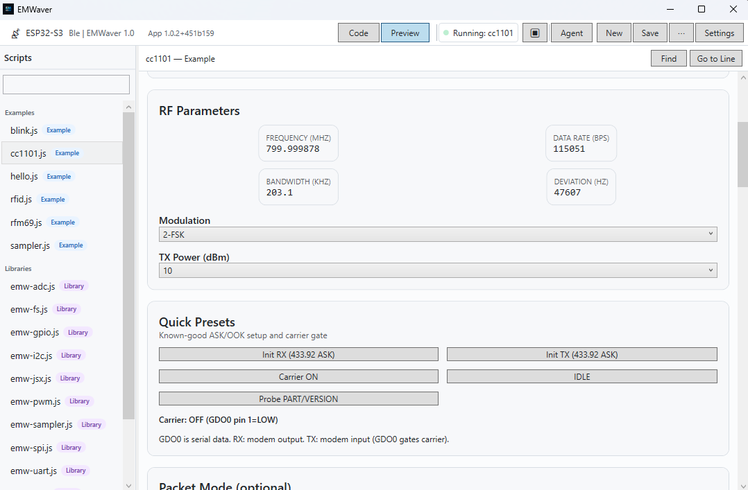
Scroll down to the Quick Presets card. Click Init TX (433.92 ASK).
This sends the CC1101 register writes for the known-good 433.92 MHz ASK/OOK transmit preset. It sets the frequency, data rate, modulation, PA table, packet/control registers, and GDO configuration. In TX mode, GDO0 becomes the carrier/data gate.
6. Verify 433.92 MHz
After clicking Init TX (433.92 ASK), go back to the first card and clickInitialize & Read again. The RF parameter tiles should now show a frequency close to 433.920000 MHz.
If you read the radio before applying the TX preset, the frequency may show the module’s previous/default configuration instead. Apply Init TX, then read again.
7. Turn on the carrier
In the Quick Presets card, click Carrier ON. The script drives the selected GDO0 pin high, which gates the CC1101 TX carrier on at 433.92 MHz.
Click Carrier OFF or IDLE when you are done testing.
Quick troubleshooting
- No CC1101 response: verify 3.3 V power, common ground, SPI wiring, and that the script’s CS pin matches your wiring.
- Frequency does not show 433.92 MHz: click Init TX, then click Initialize & Read again.
- Carrier button has no effect: confirm GDO0 is wired to the selected GDO0 pin, for example GPIO2.
- Windows app is connected but script fails: confirm the board is running EMWaver firmware and appears connected in the Device view.